Network Diagram
This part of documentation describes the network diagram for a standalone R2 where a client, represented by a browser, communicates with a server. The server is responsible for transferring rendering events from an application to the browser, as well as user events from the browser to the application.
Application: This component is typically a R2 application running in its own JVM started by the server. It generates rendering events that need to be transferred to the browser and receives user events from the browser.
R2 Server: This component acts as an intermediary between the application and the browser. It starts the application, establishes WebSocket connections, receives rendering events from the application and transfers them to the browser. It also receives user events from the browser and transfers them to the application. The R2 server can run on local machine, on premise, in the cloud or even containerized in Docker or Kubernetes environment.
Browser: This component represents the client and is responsible for receiving rendering events from the server, updating its rendering of the application, and sending user events to the server.
Communication: The communication between the components takes place over a network, and the data transfer protocol used is WebSocket. The following steps describe the communication process:
The application generates a rendering event and sends it to the server.
The server receives the event and transfers it to the browser using WebSocket.
The browser receives the event and uses it to update its rendering of the application.
The updated rendering is displayed to the user, who can interact with it.
When the user interacts with the rendering, the browser generates a user event and sends it to the server.
The server receives the user event and transfers it to the application.
The application processes the user event and updates its state.
The following diagram illustrates the network diagram for the system described above
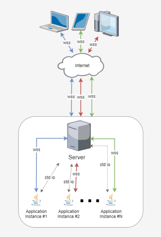
Figure: 1.0 Basic R2 on Web Architecture
R2 on Web can also be on Cluster Architecture, to know more click here.